QSM201 Construction Measurement (1 of 4) Civil & Structural Works End-of-Course Assessment 2026
QSM201 End-of-Course Assessment Jan 2026
Instruction To Students:
- This End-of-Course Assessment paper comprises SEVENTEEN (17) pages (including the cover page).
- You are to include the following particulars in your submission: Course Code, Title of the ECA, SUSS PI No., Your Name, and Submission Date.
- Late submission will be subjected to the marks deduction scheme. Please refer to the Student Handbook for details.
Important Note
ECA Submission Deadline: Wednesday, 15 April 2026, 12 Noon
Please Read This Information before You Start Working on your ECA
This ECA carries 70% of the course marks and is a compulsory component. It is to be done individually and not collaboratively with other students.
Submission
You are to submit the ECA assignment in exactly the same manner as your tutor-marked assignments (TMA), i.e. using Canvas. Submission in any other manner like hardcopy or any other means will not be accepted.
Electronic transmission is not immediate. It is possible that the network traffic may be particularly heavy on the cut-off date and connections to the system cannot be guaranteed. Hence, you are advised to submit your assignment the day before the cutoff date in order to make sure that the submission is accepted and in good time.
Once you have submitted your ECA assignment, the status is displayed on the computer screen. You will only receive a successful assignment submission message if you had applied for the e-mail notification option.
ECA Marks Deduction Scheme
Please note the following:
- Submission Cut-off Time – Unless otherwise advised, the cut-off time for ECA submission will be at 12:00 noon on the day of the deadline. All submission timings will be based on the time recorded by Canvas.
- Start Time for Deduction – Students are given a grace period of 12hours. Hence calculation of late submissions of ECAs will begin at 00:00 hrs the following day (this applies even if it is a holiday or weekend) after the deadline.
- How the Scheme Works – From 00:00 hrs the following day after the deadline, 10 marks will be deducted for each 24-hour block. Submissions that are subject to more than 50 marks deduction will be assigned zero mark. For examples on how the scheme works, please refer to Section 5.2 Para 1.7.3 of the Student Handbook.
Any extra files, missing appendices or corrections received after the cut-off date will also not be considered in the grading of your ECA assignment.
Plagiarism and Collusion
Plagiarism and collusion are forms of cheating and are not acceptable in any form of a student’s work, including this ECA assignment. You can avoid plagiarism by giving appropriate references when you use some other people’s ideas, words or pictures (including diagrams). Refer to the American Psychological Association (APA) Manual if you need reminding about quoting and referencing. You can avoid collusion by ensuring that your submission is based on your own individual effort.
The electronic submission of your ECA assignment will be screened through a plagiarism detecting software. For more information about plagiarism and cheating, you should refer to the Student Handbook. SUSS takes a tough stance against plagiarism and collusion. Serious cases will normally result in the student being referred to SUSS’s Student Disciplinary Group. For other cases, significant marking penalties or expulsion from the course will be imposed.
Answer ALL questions. (Total 100 marks)
Question 1
Interpret Figures Q1.1 to Q1.3.
(a) Prepare a take-off list including the units of measurement and relevant SMM clauses for the excavation, reinforced concrete works including formwork and reinforcements shown in the drawings and specifications.
(10 marks)
(b) Apply measurement techniques to take off quantities for all of the following:
(i) Sub-structure excavation, concrete, formwork and hardcore
(15 marks)
(ii) Sub-structure reinforcement for foundations and column stumps
(10 marks)
(c) Apply measurement techniques to take off quantities for the reinforced concrete piles.
(10 marks)
Specification Notes for Question 1:
Excavation & RC Works:
- Over site excavation works shall not be required.
- Reduced level at soffit of hardcore layer is 97.200
- Backfilling shall be from materials arising from the excavation works. All surplus excavated materials shall be disposed of site to an approved tip.
- Hardcore materials shall comprise of broken stones and concrete and compacted with a 10t mechanical roller.
- Reinforced concrete shall be of grade 40 strength.
- Lean concrete shall be of grade 15 strength.
- Formwork shall be of sawn timber.
- Ground beam shall be 200 x 200 mm deep.
Reinforcement Works:
- Concrete cover shall be 40 mm thick.
- Top bar bend allowance shall be 150 mm and 200 mm for bottom bar bend in foundation.
- Column stump main bars shall be set 190 mm into the foundation.
Reinforced Concrete Precast Concrete Piles:
- Piles shall be 175 x 175 mm RC grade 40 precast and reinforced with 4xH25mm diameter main bars with H10mm diameter links @ 150mm c/c.
- Piles are installed below all foundation at 500 mm c/c both ways and 600 mm away from the edges of the foundation.
- All piling works shall be in provisional quantities and shall commence from the EGL. The estimated driven depth is 20.00 m.
- Pile shoes shall be of chilled iron to fit pile size and weighing 25 kg.
- All piles are required to be cut at the required cut of level.
- Five working piles shall be selected for load test up to 1.5 times the designed working load of 80t.
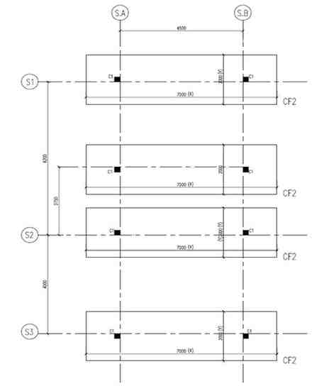
Figure Q1.1 Foundation Plan (NTS)
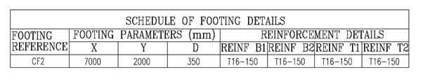
Table Q1: Schedule of Foot/Foundation Details (NTS)
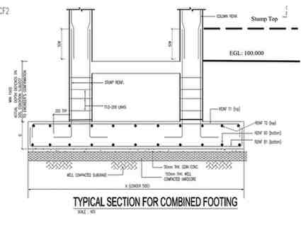
Figure Q1.2: Typical Foundation Section Details (NTS)
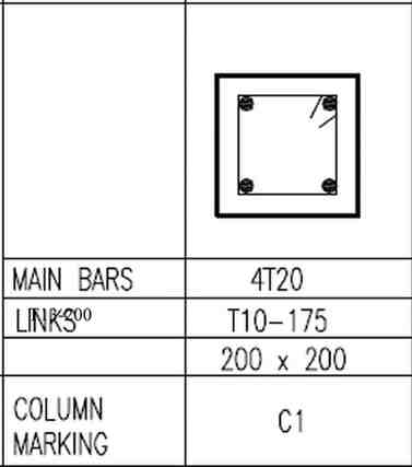
Figure Q1.3: Column Stump Details (NTS)
Question 2
Figures Q2.1 to Q2.6 shows the layout plan and details of three inspection chambers and the main drain line to be constructed. Apply measurement techniques to take off quantities for the following:
(a) Inspection chambers (3 Nos) and all associated works.
(20 marks)
(b) Main drain line (2 sections) and all associated works including testing and connections to public sewers.
(10 marks)
(c) Timber piles.
(10 marks)
Specifications Notes:
Inspection Chambers & Drain:
- Excavation for inspection chambers and drain lines shall commence from the existing ground level of 100.000 on soft ground.
- Main drain channel shall be 150 mm diameter half round vitrified clay bedded and jointed in cement & sand mortar (1:3).
- Branch channels shall be 100 mm diameter half round vitrified clay bedded and jointed in cement & sand mortar (1:3). There are 2 branch channels each in IC1, 3 in IC2 and 5 in IC3.
- Bricks shall be in Engineering bricks, laid English Bond, bedded and jointed in cement and sand mortar (1:3).
- Concrete bed shall be 100 mm thick and benching average 150mm high with (1:6 gradient) in mass concrete grade 20.
- Lean concrete shall be of grade 15.
- IC frame and cover shall be of cast iron, medium duty type to SS30, 600 x 600 x 140 mm thick
- Cement and sand (1:3) mortar rendering shall be 10 mm thick
- Precast concrete suspended slab shall be of grade 35 reinforced concrete and reinforced with a layer of A10 Fab Mesh.
- Step-iron for access shall be of 20 mm diameter x 225 mm wide cast iron, Ushape and built into IC walls. Each IC shall have to access step-irons.
- Main drain line shall be 150 mm diameter cast iron pipe. Pipe thickness is 13mm.
- Concrete cover shall be 50 mm thick.
Piling Works
Timber piles:
- Piling works shall be in provisional quantities.
- Piling works shall commence from the existing ground level 100.000.
- All piles are 100 x 100 timber tanalized piles.
- The estimated driven depth of piles is 9.00 m. Supply length of piles is 4.00m long.
- Piles for Inspection Chambers shall be spaced at 450mm c/c in both directions on plan. The first and last pile is place at 250 mm away from the edge of the base slab.
- Piles for main drain line shall be installed in a single row, each pile space at 450mm c/c apart. The first and last pile is 250 mm away from the edge of the concrete base slab, both ways.
- Working load test shall be executed up to 1.25 times the design working load of 25t on 5 selected working piles.
- All piles shall be cut off at the required cut-off level as specified.
- Pile shoes shall be of mild steel plate 5 mm thick to suit pile size.
- Box sleeve joints shall be of mild steel, 100 x 100 x 3 mm thick x 400 mm long and coated with two coats of bitumen paint.
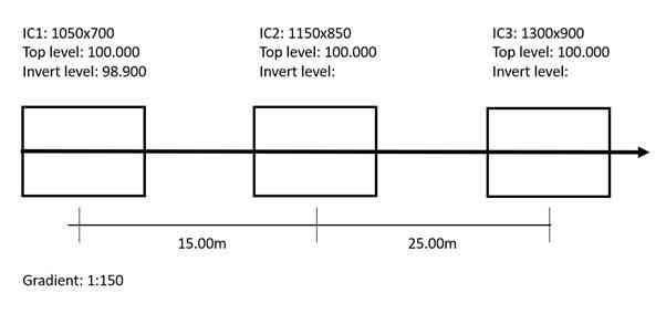
Figure Q2.1: IC/Drain Layout Plan (NTS)
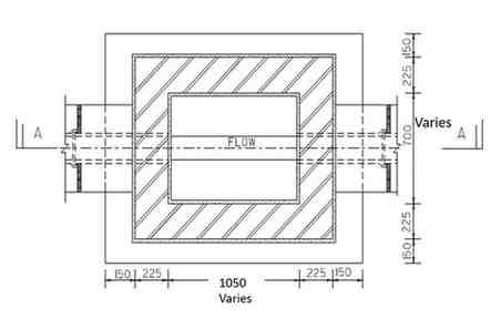
Figure Q2.2: Typical IC Plan (NTS)
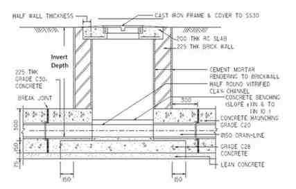
Figure Q2.3: Typical IC Section on Hard Ground (NTS)
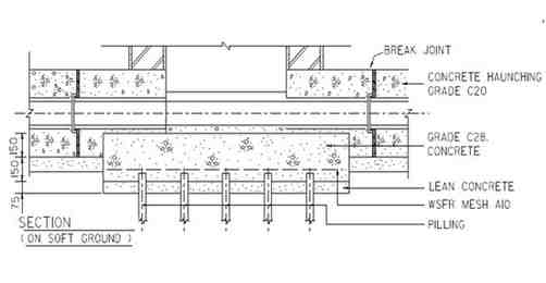
Figure Q2.4: Details of IC Section/Piles on Soft Ground (NTS)
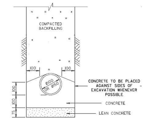
Figure Q2.5: Details of Pipe Support (NTS)
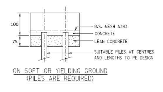
Figure Q2.6: Details of Piles on Soft Ground (NTS)
Question 3
With reference to Figures Q3.1 to Q3.5, take off quantities for the triangular roof truss and roof purlins including all associate fittings and plates. (Note: Internal members of roof truss length can be determined using trigonometry or Pythagoras theorem. Where such length cannot be determined, students are to make reasonable assumptions and to state them clearly).
Specification Notes:
- The proposed building is a double story steel framed structure, overall height 15.00m.
- All connections for the truss are site welded.
- Weight conversions for steel members are not required to be calculated.
- Truss rafters protrude about 125mm from column face.
- Steel columns are not required to be measured.
(15 marks)
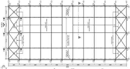
Figure Q3.1: Roof Plan (NTS)
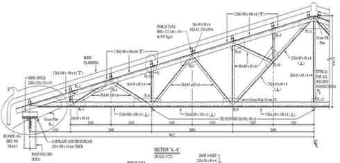
Figure Q3.2: Roof Truss (NTS)
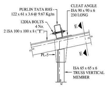
Figure Q3.3: Purlin Details (V) (NTS)
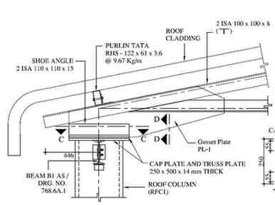
Figure Q3.4: Cap/Truss Plate Detail (U) (NTS)
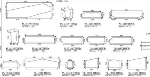
Figure Q3.5: Gusset Plates Details (NTS)
—– END OF ECA PAPER —–
The post QSM201 Construction Measurement (1 of 4) Civil & Structural Works End-of-Course Assessment 2026 appeared first on Singapore Assignment Help.