| Power Electronics Systems |
Objectives:
- To undertake a mini-research and write a brief on the operation principle of a single-phase half-controlled bridge rectifier converter.
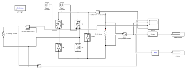
- Using the provided circuit parameters to simulate and evaluate the performance of the single-phase half-controlled bridge rectifier in MATLAB/SIMULINK
- To undertake a mini-research and write a brief on the operation principle of a DC/DC buck converter.
- Using the provided circuit parameters to simulate and evaluate the performance of the buck converter in MATLAB/SIMULINK
- Shows the circuit diagram of a single-phase half-controlled bridge rectifier with an RL load. As shown, it consists of thyristors (T1 and T2), the diodes (D1 and D2), and a freewheeling diode, FW.
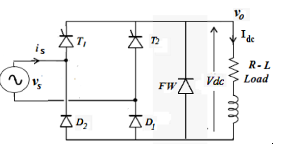
- By citing relevant literature, and using relevant waveform diagrams, explain the working principle of the circuit including the role of the freewheeling diode
- By referencing relevant waveform diagrams, derive the expression for the average load voltage,, the RMS load voltage, the average current, and the RMS load current, of the circuit for a purely resistive load [when L=0]
- Build the circuit in SIMULINK and simulate the operation of the rectifier with a purely resistive load, the supply voltage of, supply frequency of 50Hz, and the thyristor firing angle set to(). Present the graphs of your simulation results. Comment on the output voltage and current waveform profiles. Can it be used to power a DC circuit (like a DC motor) in its current form? Explain
- Compare the measured average and the RMS output voltage with the calculated values obtained using the expressions derived in (a)(ii) above. Discuss your findings?
- Now update the load by connecting an inductor in series with the load. Simulate the circuit operation with and present your output voltage and current waveforms and the average and RMS output voltage values. Compare the obtained values with the measured values obtained in (b) (ii) above. Discuss your findings.
- Repeat b(iii) above with and present the output voltage and current waveforms. Also, present the average and the RMS values of the output voltage and current. Explain the effects of the change of firing angle to the average output voltage and current profiles and magnitudes.
- Increase the load inductance to and repeat step (b)(iii) above and present the average output voltage and current waveforms. Compare the results with the ones obtained in (b) (iii) above. Explain the effects of change of inductance in the load to the average load current profile.