Assignment Details:
Inverted pendulum: design, model, build and control
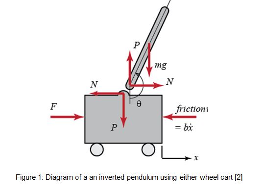
In this part, your group will design and simulate an inverted pendulum. The figure below shows an example of balancing an inverted pendulum by moving a cart along a horizontal track. Other implementations are also possible such as the Boxing bot which combines the structure of a mobile robot and an inverted pendulum system. You can also look into other types of inverted pendulums such as the Segway or overhead crane [1].
You have to develop an inverted pendulum model and controller. When put into its upper equilibrium position, the pendulum will be able to autonomously balance by returning to that position after (a ‘reasonable’) amount of disturbance is applied to the pendulum.
A wide range of sensors and actuators including servo motors, gyroscopes sensor, angle sensor, accelerometer, ultrasound, color sensor, and the camera should be investigated.
TASK 1
Mechanical design and modeling
Note: Your mechanical design will affect both the electrical and control aspects of the system. Several designs may be adopted to achieve the inverted pendulum. Any change in the physical properties of the vehicle immediately causes changes in system behavior.
- Provide a short literature review including sketches of some potential designs.
- Describe the kinematics of the chosen mechanical design.
- Discuss the effects of the mechanical design on the dynamics of the system (e.g. the effect of the pendulum link length and mass, the effect of motor friction compared to other sources of friction, the effect of placement of components to adjust the center of mass, etc.).
TASK 2
Sensors and actuators
There are a number of different sensors that can be used to measure the disturbance, including, angle sensor, gyroscope, accelerometer, ultrasound sensor, vision subsystem, light sensor and color sensor.
- Provide investigate and document (including technical specifications) how each of the sensors works in theory.
- Compare the different sensors based on the investigation and assess their suitability for the task.
TASK 3
Computer vision
- Develop an algorithm using image processing techniques to identify the angle of disturbance to an inverted pendulum. Techniques may include image subtraction, filtering, and feature extraction such as Hough transform, color processing, or AI classification.
- Test your algorithms using both still frames with known angles and a video recording.
- Note that the default parameter settings are not necessarily the best. List the tunable parameters and explain how you set each one. Provide a strategy to achieve the most accurate results.
- Comment on the accuracy and limitations of computer vision as a tool for the inverted pendulum task.
- Provide commented printouts of your m-files within the report.
Task4
Modelling and Control
- Discuss the approximate linear model to describe the system (this involves taking into account relevant dimensions, weight, and friction).
- Formulate a PID strategy capable of stabilizing the inverted pendulum.
- Simulate in Matlab/Simulink and provide a critical discussion on the results.
- Provide the printout of commented m-files/Simulink diagrams.
Task5
Fuzzy control
- Formulate a Fuzzy logic strategy and implement it in Matlab.
- Explain the design and tuning process followed.
- Comment on the results.
- Provide the printout of the Fuzzy design.
- Compare and discuss the results with respect to task 4.
Task6
Demonstration – video program performance test
- Record a video clip (maximum 6 minutes)including all the aspects of your design (A-E):
- Compare different designs and explain the most suitable approach
- Explain which sensors and actuators should be used for real implementation.
- Describe your controllers and present simulations. Please note that conditions should include disturbances to be applied to the inverted pendulum that should be able to stabilize.
- Show the results of the computer vision program and explain the methodology adopted and parameter tuning.